Solidworks Datum Plane in Drawing
A frequent question about 3D annotations is how a datum symbol tin be attached to a centerline, an axis or a middle aeroplane of solid bodies. This SOLIDWORKS MBD forum postal service provides a contempo instance. Datum features are the foundation of composing and interpreting geometric dimensioning and tolerancing(GD&T) definitions. When we locate a physical accost on a map, nosotros reference the country, state, city and street of the address. Datum features provide similar references in a feature control frame. So let'south expect into this important topic in this commodity.
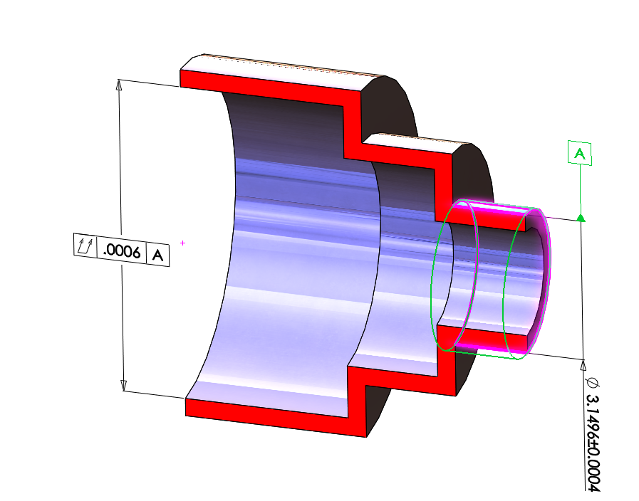
We can begin by asking the question: Do yous see whatsoever problem with the GD&T definition in Figure 1? In the effigy, datum symbol A is attached to a centerline and so is referenced in a full runout tolerance.
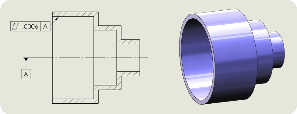 Effigy 1. A problematic GD&T definition. (Image courtesy of a Tec-Ease GD&T tip video.)
This actually turned out to be a 1000000-dollar problem. The original part past a client was a lens barrel in a infinite telescope on which the opening at the left interfaced with a lens, which is why the total runout tolerance was controlled tightly at 0.0006 inch. Figure 1 is a simplified illustration of the office.
A tight tolerance is fine as long as the product function justifies it. The real problem with this part is the datum label attached to the centerline on the client drawing, because it didn't specify which tangible characteristic would serve as the datum feature to inspect the tight tolerance. A centerline is theoretical and intangible. In the actual production, the supplier inspector didn't have definitive instructions on how to hold the part. Figure two shows an exaggerated instance of a machined part by the supplier. Clearly, the smaller cylinder on the correct of the figure was misaligned.
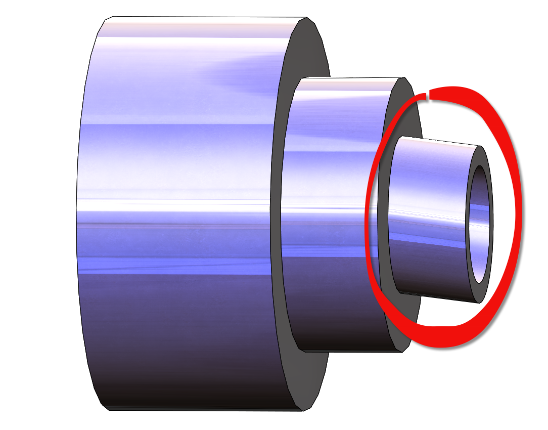 Figure 2. An exaggerated example of a machined part.
If the supplier grabs a user-friendly characteristic such as the larger outer cylinder on the left, spins the function, then inspects the runout, the part is good as what is shown in Effigy 3.
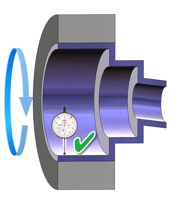 Figure 3. Inspecting the full runout by holding the user-friendly larger outer cylinder.
Unfortunately, the customer held the butt in the way it would assemble in the lens mount. As a issue, the smaller cylinder on the right should be spun to audit the office based on the intent of the design. Now, as shown in Figure iv, the total runout is violated and the part should be rejected. This ambiguity led to a lawsuit of nearly$8 million.
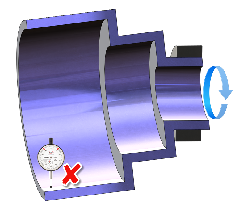 Effigy 4. Inspecting the full runout past holding the smaller outer cylinder.
This trouble could have been easily avoided if the symbol was specifically defined to an intended tangible characteristic, rather than an ambiguous geometry. Figure v shows the recommended definition using SOLIDWORKS MBD. In this approach, you can select the smaller outer cylinder to define the characteristic. The software then highlights the actual face in one case a label is selected and automatically aligns the datum symbol to the size bore and tolerance callout.
 Effigy v. A recommended datum characteristic definition.
This lens butt example demonstrates the costly downside of cryptic GD&T definitions. Although this event can occur in both 2D drawings and 3D annotations, some MBD software guides the definitions with congenital-in GD&T rules to ensure solid practices. For instance, Johnson Controls estimated significant value benefits with improved GD&T practices in the CATIA MBD environment.
Similarly, SOLIDWORKS MBD follows the ASME Y14.v-2009 GD&T standard closely. For case, co-ordinate to this standard, the datum characteristic symbol B in the two figures when compared to Figure 6 conveys two completely unlike pattern requirements. The one shown on the left indicates that datum feature B is the width feature because the label B is aligned with the width dimension line, while the 1 shown on the right indicates that datum feature B is only a unmarried face because the characterization is not aligned with the width callout.
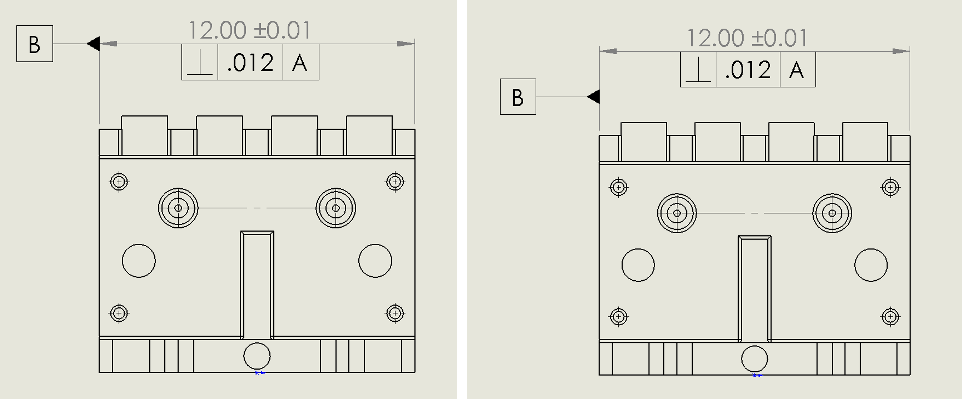 Figure 6. A drawing comparison betwixt a width characteristic every bit a datum feature (left) and a single face as a datum feature (right).
In gild to avoid this common confusion, SOLIDWORKS MBD automatically aligns the label to the width feature size dimension line every bit shown on the left of Effigy vii. If the design requires just a confront as the datum characteristic, and then you can define a confront, rather than a width.
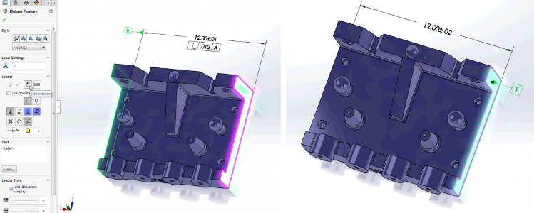 Effigy vii. An MBD comparison between a width as a datum feature (left) and a single face as a datum feature (correct).
By the way, a width datum feature gives the heart aeroplane between the 2 opposing faces as the theoretical datum. I promise this answers the frequent question posed at the beginning of this commodity. You tin can find more virtually the differences between datum feature and datum here.
Let's aggrandize to several other examples. Figure 8 shows the datum features A, B and C on a shifter stick. A is the width size feature, B is the two coplanar shoulders as highlighted in dark-green, and C is the pattern of two mounting holes that is supported by a new enhancement in SOLIDWORKSM MBD 2018.
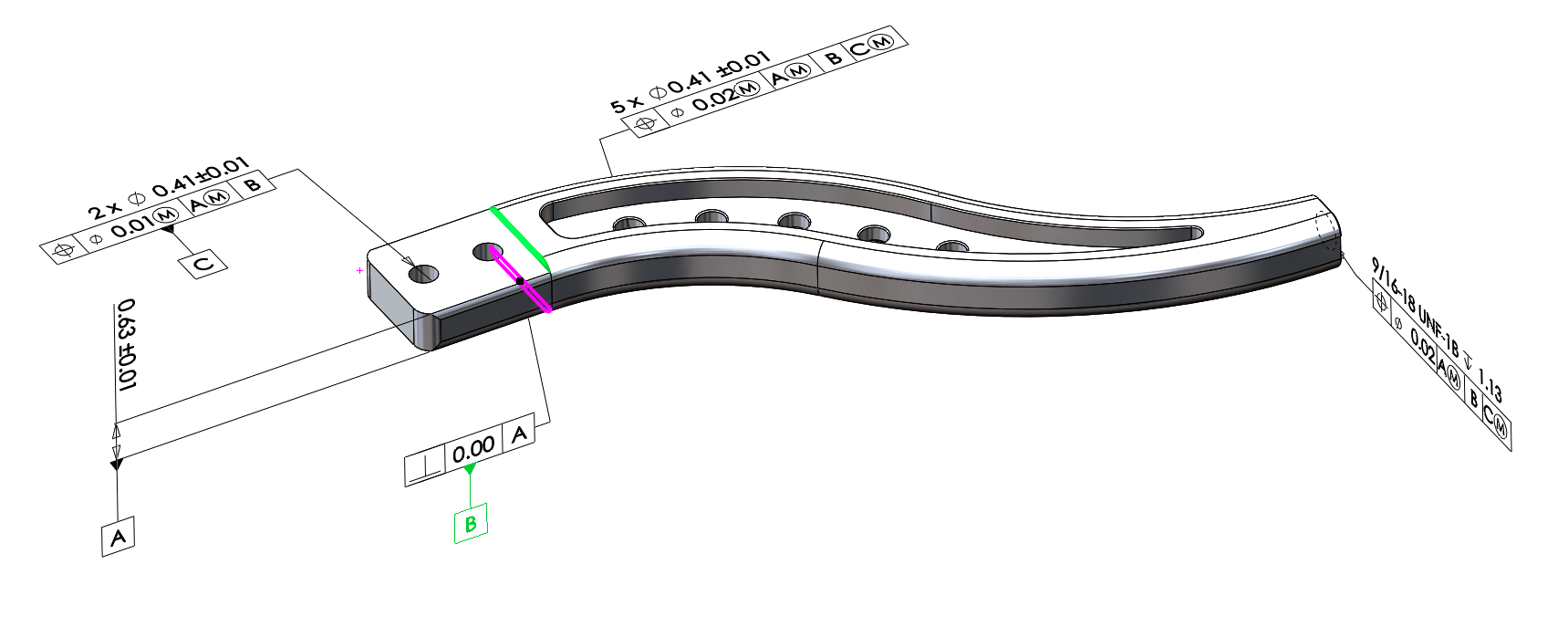 Figure 8. Datum features A, B and C on a shifter stick.
In this ABC datum framework, I added the Maximum Cloth Purlieus (MMB) modifiers to A and C, which are size features. This allows datum shifts to accept more than good parts. However, if I were to add MMB to datum feature B as shown in Figure 9, the software would flag information technology because B is not a feature of size and maximum cloth boundary doesn't utilise in this example.
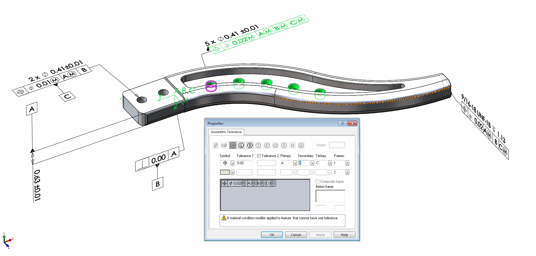 Figure 9. A warning bulletin against using an incorrect MMB modifier.
You may also discover that when a characteristic control frame is selected, the coordinate organization as defined past the ABC datum references is automatically created and highlighted in green in the graphics area. This provides an instant visual confirmation that makes interpretation easier. It too helps automate the coordinate arrangement alignment for other downstream manufacturing software.
On this GD&T editing dialog, if a user forgets to type in a master or secondary datum letter of the alphabet before a 3rd one in a feature control frame, the dialog automatically displays a warning message to alert the user as shown in Effigy 10.
 Effigy x. A warning message most missing primary or secondary datum letters.
Besides the transmission annotations, the software follows the GD&T rules in the automatic dimension creation every bit well. Figure 11 illustrates an error in which the two datum features in the red box share the aforementioned axis. The features are defining the same theoretical datum, so the tool catches their unnecessary duplication.
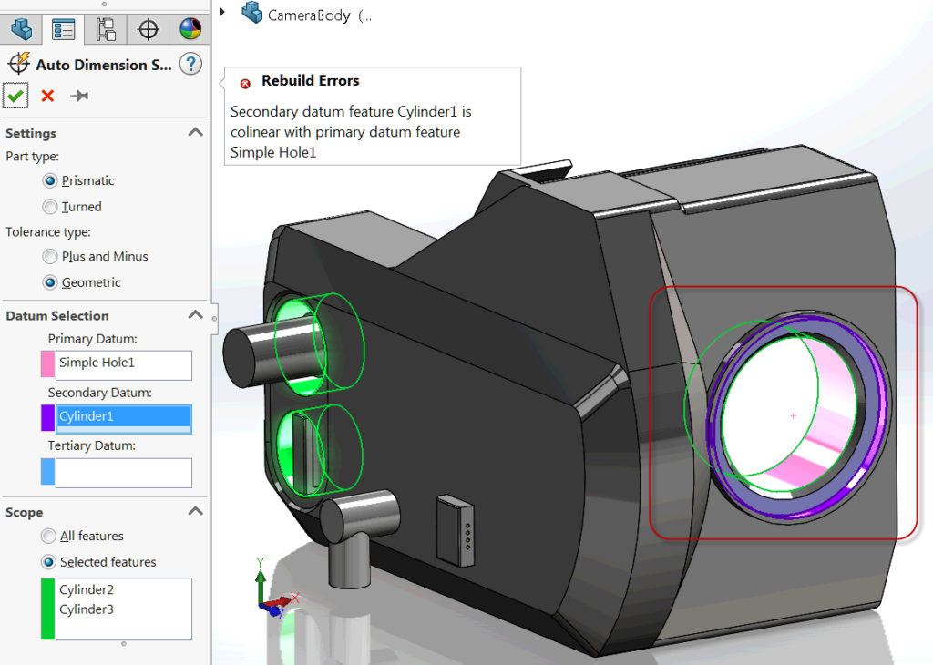 Effigy 11. An unnecessary datum characteristic duplication defenseless in the automated dimension scheme.
As mentioned at the beginning of this mail service, when interpreting a GD&T definition, a user first needs to remember the datum references. So, a handy command is to automatically highlight the associated datum symbols and features. The 3D PDF generated by SOLIDWORKS MBD provides this command shown in Figure 12. You can right-click on a feature command frame and click on the context menu command "Highlight associated datums." I hope that a similar handy capability can exist added to the SOLIDWORKS environs in the future.
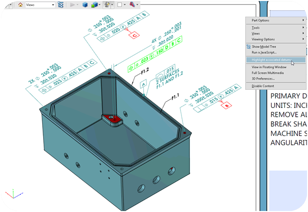 Figure 12. Highlight associated datum symbols and features for a feature control frame.
With that, let's conclude this commodity with several key points:
- Datum features are the foundation of GD&T definitions.
- Yous should ascertain datum features on tangible faces, rather than intangible ambiguous geometries.
- SOLIDWORKS MBD builds GD&T rules into the software to assist observe violations.
If y'all accept any comments or questions, please feel free to leave them in the comments area below. To learn more near how SOLIDWORKS MBD can assist implement your Model-Based Enterprises, delight visit its product page.
Well-nigh the Writer

Oboe Wu is a SOLIDWORKS product director with 20 years of experience in technology and software. He is an advocate of model-based enterprise and smart manufacturing.
Source: https://www.engineersrule.com/ensure-solid-gdt-datum-practices-solidworks-mbd/
0 Response to "Solidworks Datum Plane in Drawing"
Post a Comment